


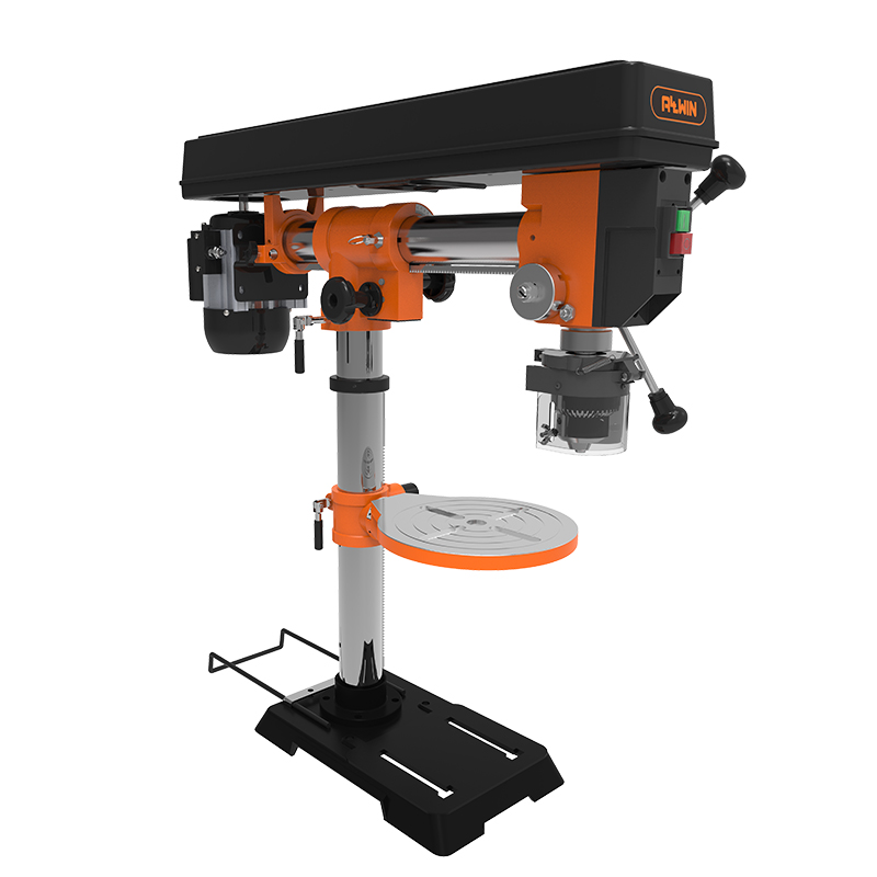
Base
The base is bolted to the column and supports the machine. It may be bolted to the floor to prevent rocking and increase stability.
Column
The column is accurately machined to accept the mechanism that supports the table and allows it to raise and lower. The head of the drill press is attached to the top of the column.
Head
The head is the portion of the machine that houses the drive and control components including the pulleys and belts, quill, feed wheel, etc.
Table, table clamp
The table supports the work, and can be raised or lowered on the column to adjust for different material thicknesses and tooling clearances. There is a collar attached to the table that clamps to the column. Most drill presses, especially larger ones, make use of a rack and pinion mechanism to allow the loosening of the clamp without the heavy table sliding down the column.
Most drill presses allow for the table to tilt to allow for angled drilling operations. There is a lock mechanism, usually a bolt, that holds the table at 90° to the bit or any angle between 90° and 45°. The table tilts both ways, and It is possible to rotate the table to a vertical position to end-drill. There is usually a tilt scale and pointer to indicate the angle of the table. When the table is level, or at 90° to the shaft of the drill bit, the scale reads 0°. The scale has readings to the left and right.
Power on/off
The switch powers the motor on and off. It is usually located on the front of the head in an easily accessible location.
Quill and spindle
The quill is located inside the head, and is the hollow shaft that surrounds the spindle. The spindle is the rotating shaft that the drill chuck is mounted on. The quill, spindle and chuck moves up and down as one unit during drilling operations, and is attached to a spring return mechanism that always returns it to the head of the machine.
Quill clamp
The quill clamp locks the quill in position at a particular height.
Chuck
The chuck holds the tooling. It is usually has three jaws and is known as a geared chuck meaning it uses a geared key to tighten the tooling. Keyless chucks may also be found on drill presses. The chuck is moved downward by means of simple rack-and-pinion gearing worked by the feed wheel or lever. The feed lever is returned to its normal position by means of a coil spring. You can lock the feed and pre-set the depth to which it can travel.
Depth stop
The adjustable depth stop allows holes to be drilled to a specific depth. When in use, it allows the quill to be stopped at a point along it’s travel. There are some depth stops that allow the spindleuck to be secured in a lowered position, which can be useful when setting up the machine.
Drive mechanism and speed control
Woodworking drill presses commonly use stepped pulleys and a belt(s) to transmit force from the motor to the spindle. In this type of drill press, the speed is changed by moving the belt up or down the stepped pulley. Some drill presses use an infinitely variable pulley that allows for speed adjustments without having to change belts as in a stepped pulley drive. See Use of the drill press for instructions on adjusting speeds.
Please send message to us from the page of “contact us” or bottom of product page if you are interested in drill press of Allwin power tools.
Post time: Feb-28-2024